Making a new headlight wiring harness

The parts that I ordered to finish up the turn signal install were supposed to be delivered today. I didn’t want to waste half a day of good weather waiting on the mail lady, so I decided to make a new headlight wiring harness.

I started off by marking (on masking tape) all of the wires whose number tags I could read.

img_20200210_1118322598788344118794600001.jpg

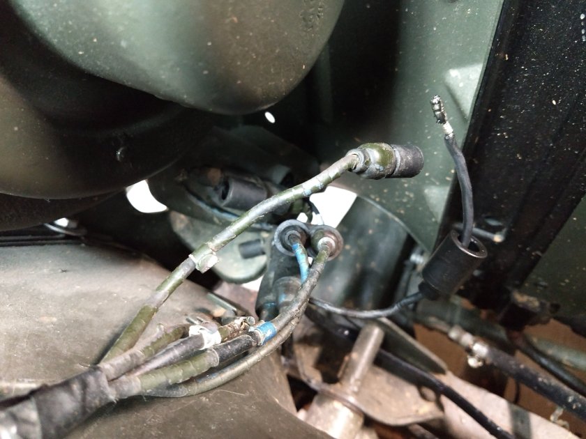
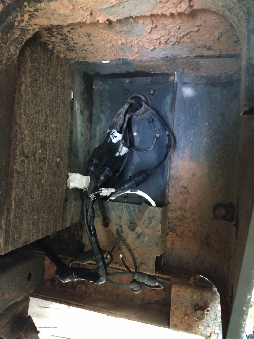
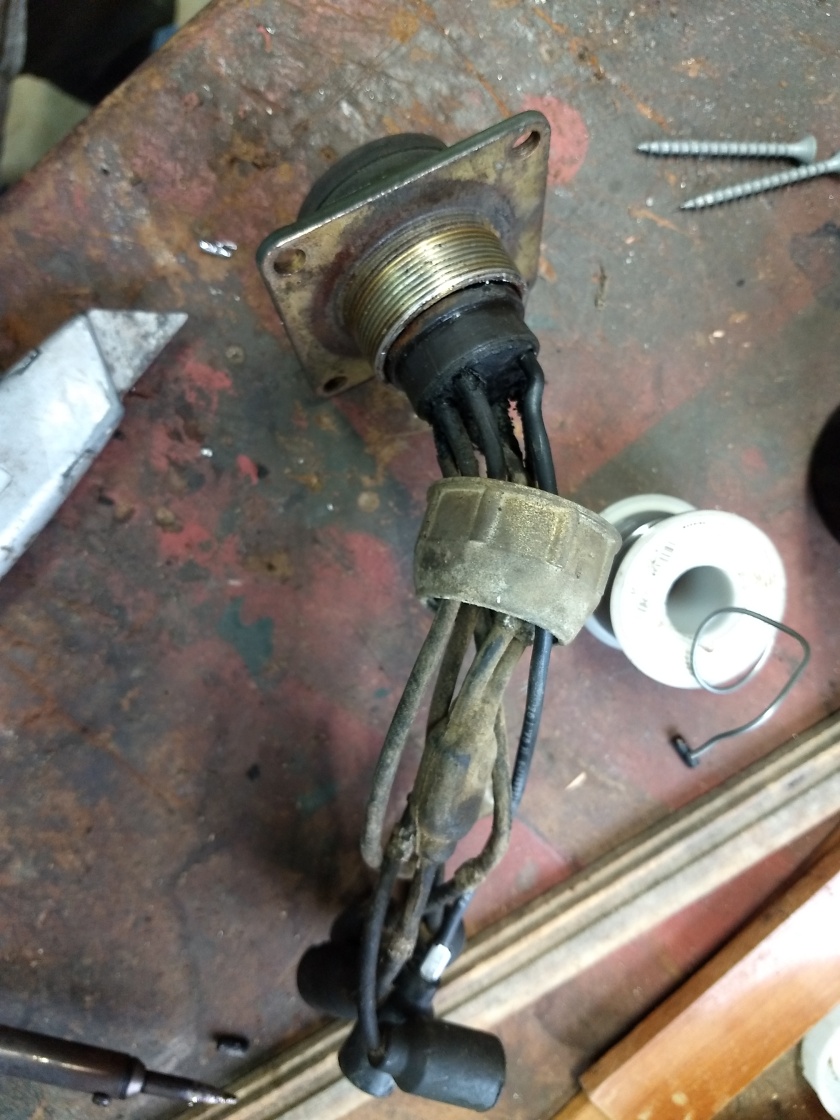
I had to scrape paint off of most of them, but still couldn’t read a few. Then I disconnected and removed the main harness.

img_20200210_1123298328497431409285566736.jpg

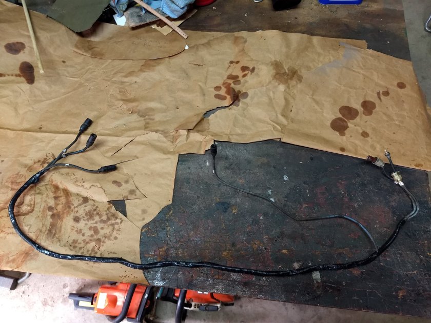
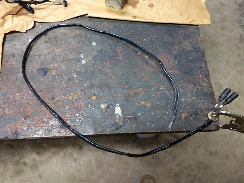
I looked through all of my new wire segments that I pulled from the M35a2 harness and found one that was the EXACT measurement I needed (100 1/2″) and had a male shell on each end. I cut it in half to make the 2 headlight wires. Next, I found another wire with a male shell that was 65″ long and cut it to 56″ for the right B.O marker light (now right turn signal). Then I taped them together with wiring harness tape. I couldn’t install the ends on the other side until the mail came with my new ends.

Next, I pulled the right headlight out to replace the Douglas connectors on the headlight pigtails. I say “pigtails” because I am using more readily available headlights with a 3 prong plug instead of the wires being attached to the bulb itself. I already had 3 pigtails with female shells, so I used butt connectors and shrink tubing to connect them to the 3 prong plug. I also removed the ground wire from the right headlight and fabbed a new one. Sorry, I didn’t take pics of this.

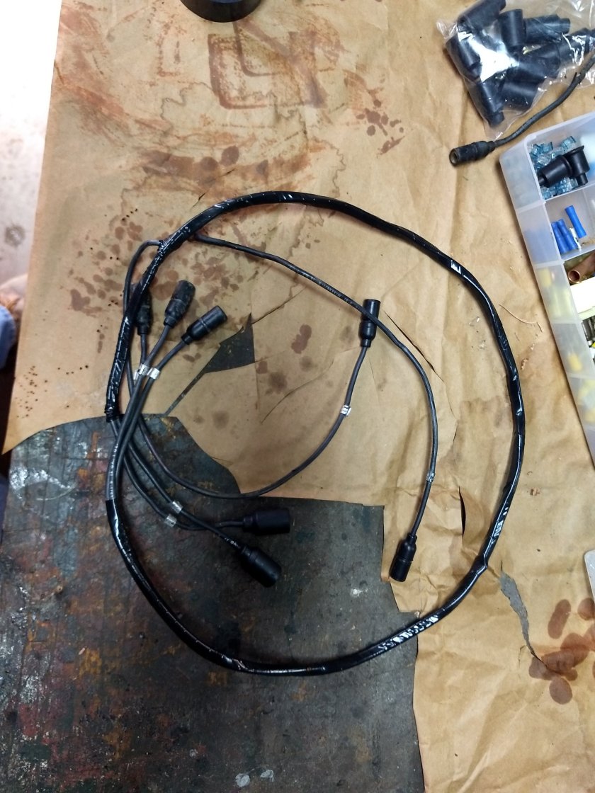
My new parts and connectors showed up, so I was able to finish up all of the new wiring with the rest of the male and female ends. I installed a male shell for the right B.O. light (turn signal) to finish up the main headlight harness. I cleaned up some of the old number tags and used some new ones from the new wires.

img_20200210_143014554_burst000_cover_top2860870606812571055.jpg

On the driver side headlight, the wires go directly from the main wiring harness (single to double “Y”s) to the headlight housing. These wires were 25″ long measured from end to end of the connectors. I found a couple of wires with ends already attached and just added female shells to the other ends. I also made a new ground wire.

When installing the new female shells (male ends), I strip the insulation back 1/4″ and flux the wire. Then I cut 1/4” piece of solder and drop it in the wire end hole. Holding the male end with pliers, I hold it over a propane torch until the solder melts, then stick the wire into the end. Hold it until it cools, then you’re ready to go! For the male shells, you can either crimp it or flux the wire, hold the end with pliers over the torch and solder the wire into the end. Nope – didn’t take any pics of this process either!

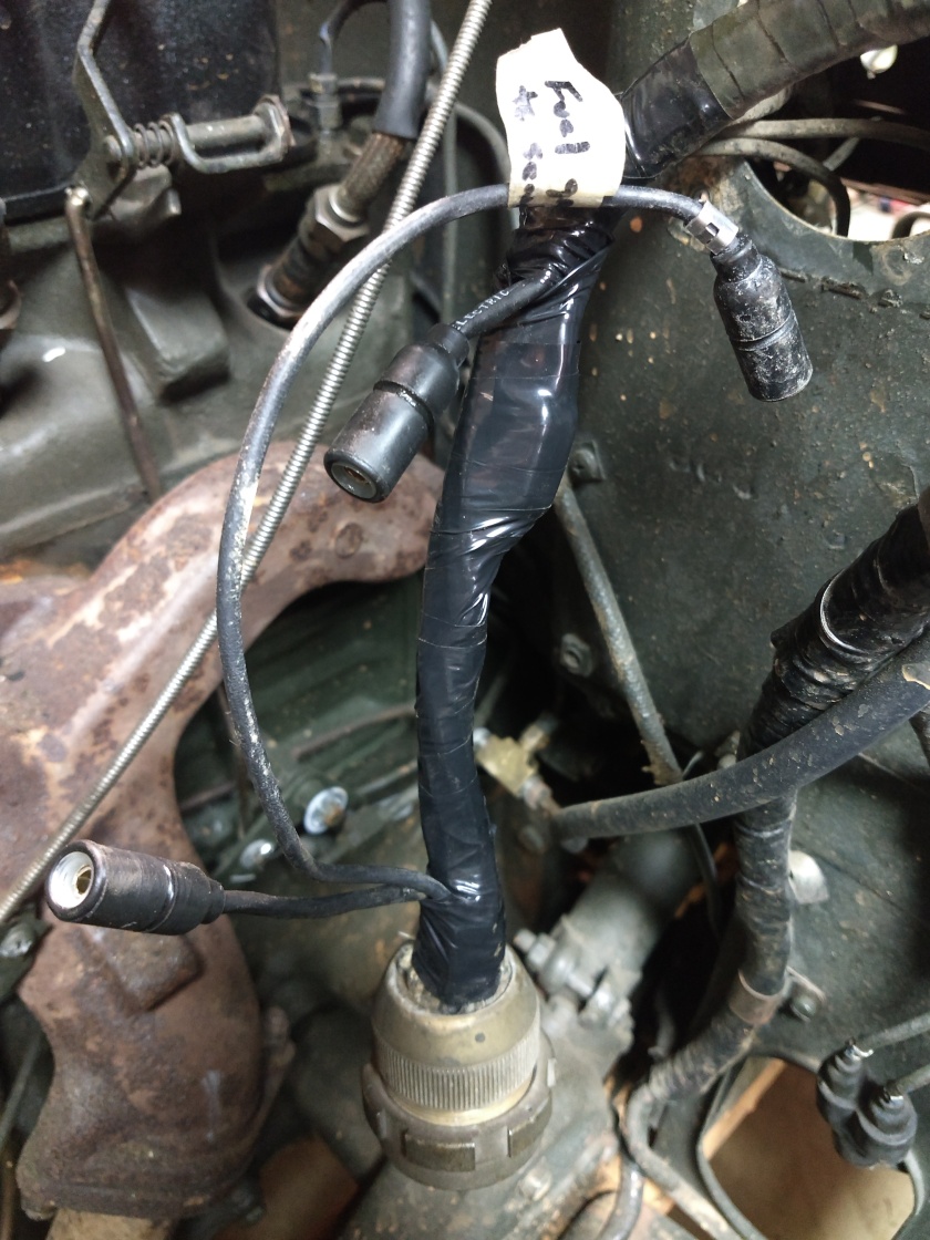
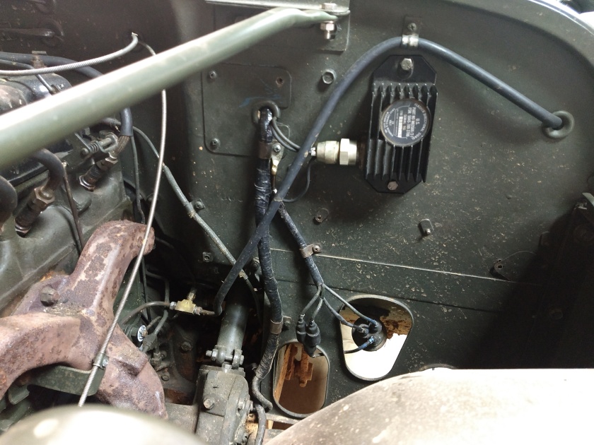
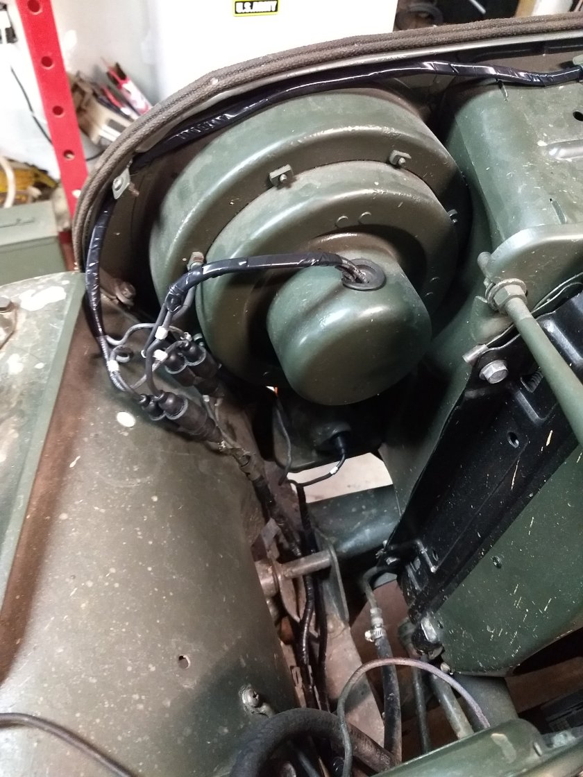
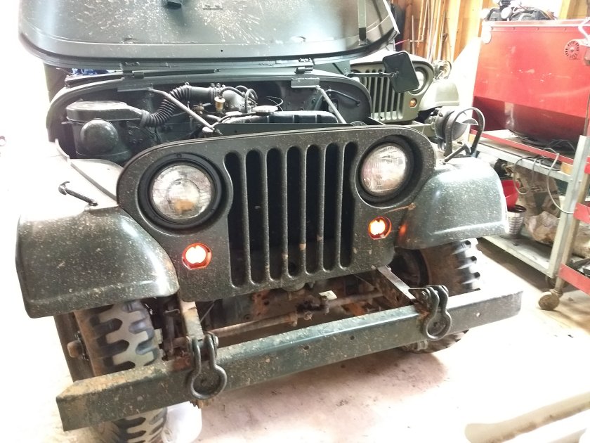
After all of the ends were on, I installed the main harness starting at the right headlight. I attached the headlight pigtail to the harness and clamped the connectors in the headlight bucket. Then I installed the new ground wire and ran all of the wires through the 3 hole grommet. I plugged in the B.O. light wire. I found that a drop of silicon on the male ends makes install/removal MUCH easier!

img_20200210_1610406163693578706980622543.jpg

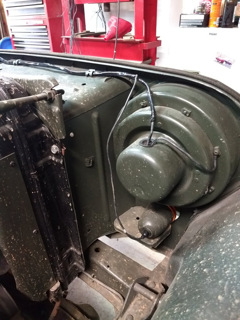
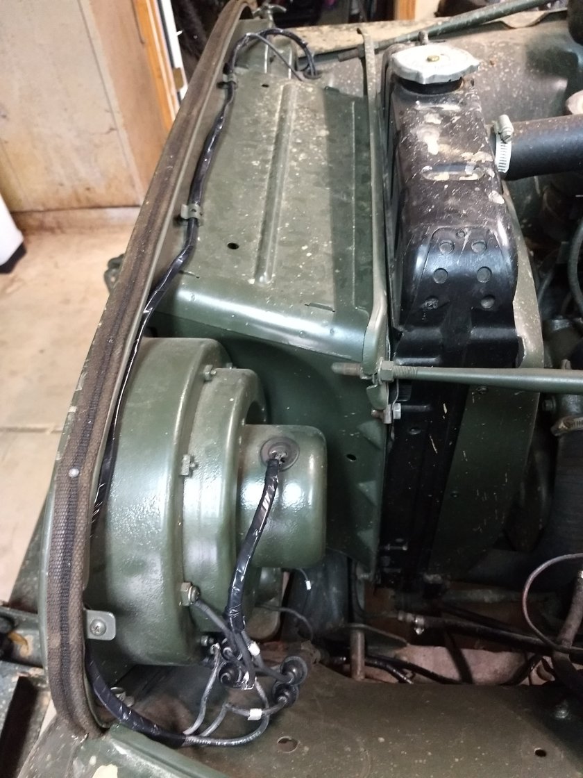
Then I could route the harness through the clips on the grill to the left headlight. I plugged the male ends into the “Y’s under the left headlight and the female B.O. light wire. I connected the left headlight bulb to the new wires, clamped them into the headlight bucket and ran them through the grommet out to the main harness “Y”s and connected them. I taped up a 6” section of these 3 wires to make it look a little better.

img_20200210_1609494082901723423051245524.jpg

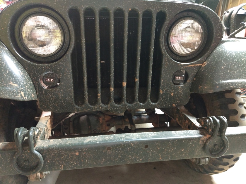
I think it turned out alright, and ready for another 55yrs of service! PLUS it’s MUCH safer!

img_20200210_1610134151807427383944615345.jpg

Next, I got into the rest of my new parts.

img_20200210_1517264842220087410162258688.jpg

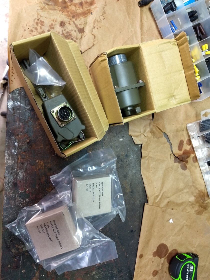
The orange turn signal kits came from Saturn Surplus (off eBay).

img_20200210_1519576366612995324156428759.jpg

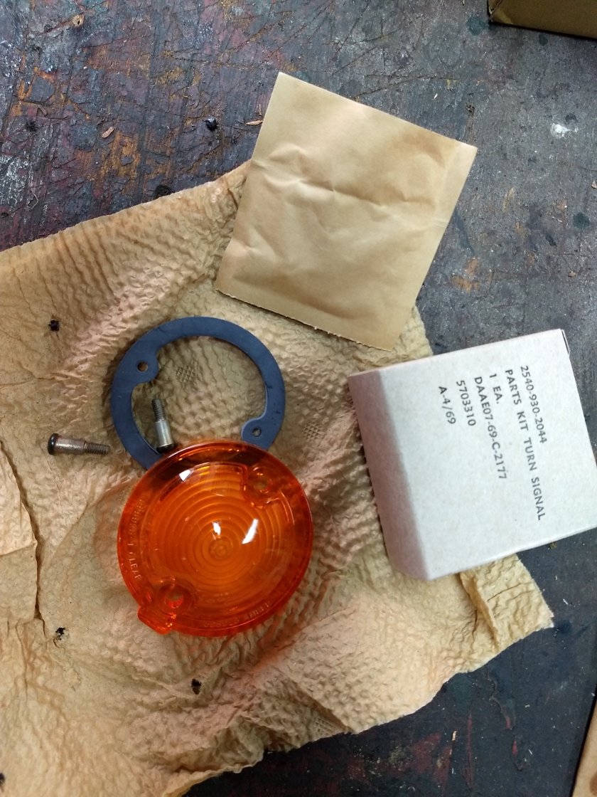
They were easy enough to install – no writeup needed:

img_20200210_1529319287739783000391808233.jpg

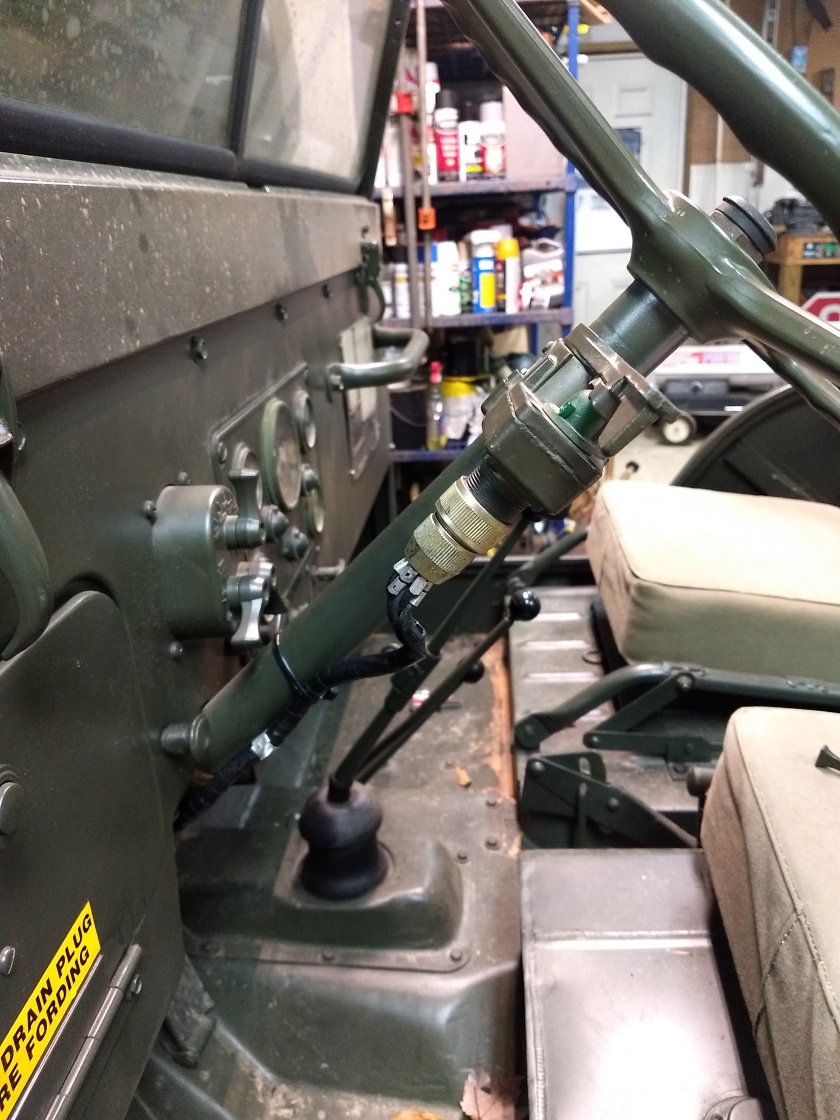
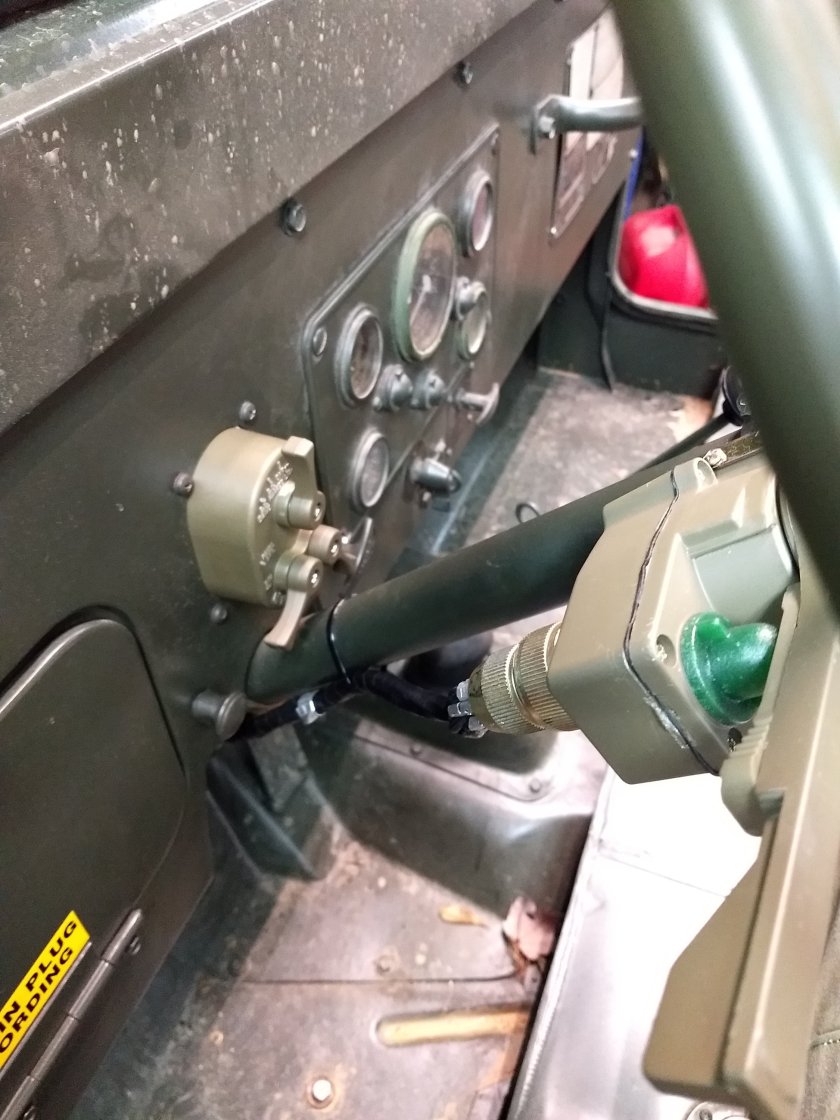
The turn signal and headlight switches came from Big Mikes Motor Pool. I’m pretty sure they are Chinese repops judging from the packaging and absence of markings. Despite that fact, once installed, they work fine with the turn signal switch being pretty tight and has a distinct notchy feel compared to the worn out original one I have on my other Jeep.

img_20200210_1602046956283950642147127696.jpg

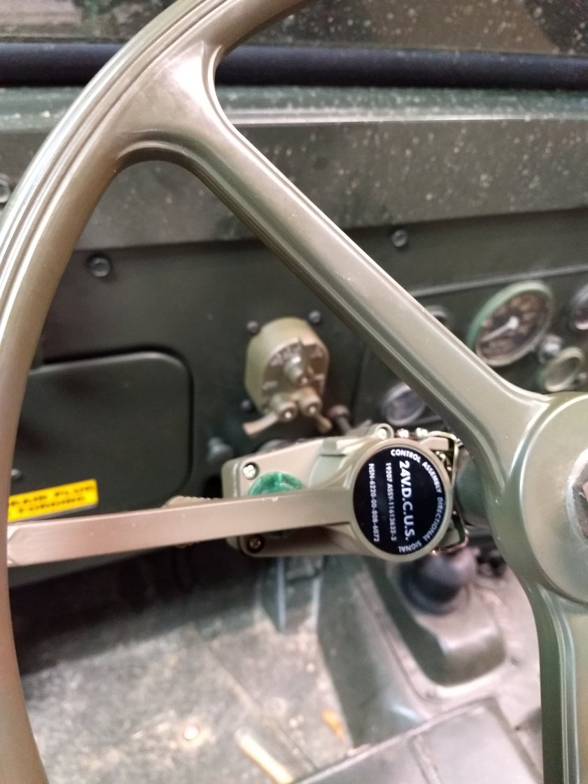
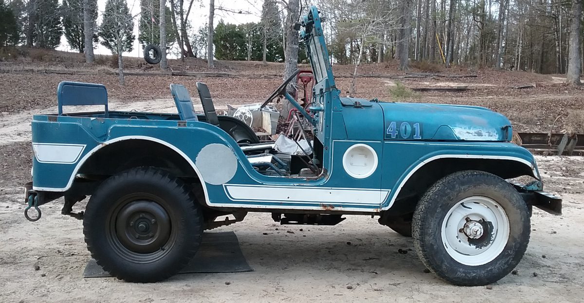
I left them in their original paint for a couple of reasons: 1) I wanted it to LOOK like turn signals were added after the Jeep was in service and 2) I didn’t feel like painting them! Tell me what you think in a comment – should I leave them as is or paint them?

img_20200210_1602207411129084072696294861.jpg

As far as wiring goes, I still want to make a new regulator harness. This is one of the main harnesses that cause fires (because it carries the high power from the regulator). I might do that the next time I’m off because I still have PLENTY of wire and now have a bunch of new ends. I will look around to see what else needs to be rewired as I go.


Turn signal wiring finished

Today I finished wiring up the turn signals. NOT as easy as it sounds of course!

By “Finished wiring”, I mean getting the trailer turn signals working too. This was a little more involved than I was hoping. When I tested the trailer turn signals, I found that the right side wasn’t flashing. After doing a little investigating, I found that the trailer was wired correctly all the way to the IV cable.

Next, I pulled the left rear tire and the wiring shield to check the trailer receptacle wiring. That’s where I found the problem. Although it has the newer style rubber connectors, it DID NOT have the wire to the “J” pin (turn signal power wire). So that’s where the saga begins.

Of course all of the rubber connectors were “welded” together and trying to get them apart resulted in the rubber breaking apart. The wires (vehicle side and receptacle side) were also very brittle and fell apart when you flexed them. After I separated all of the connectors I decided I needed to replace a lot of the brittle wire and connectors. I found a few short pieces of wire from my M35 harness with male ends attached, so I cut the old brittle ones off of the vehicle side and splicedĀ  (with butt connectors and shrink tubing) new ends on. While I was working on the vehicle side, I cut the new 22-460 wire going to the right side light and spliced in a piece of wire with a new end going to the trailer receptacle. Then I wrapped the new wire up with the old harness with wiring harness tape. I also re wrapped the harness end with the new wires.

IMG_20200206_140103973

Next, I removed the trailer receptacle from the Jeep. Once on the bench, I removed the nut and pried the rubber plug away from the back of the receptacle so that I could install the new “J” wire. I soldered a new wire into the pin and reassembled everything. Once re installed onto the Jeep, I began hooking the wires back up. Since most of the wire tags were unreadable, this was a hit and miss deal. I used the multimeter to find which wire was hot when the lights were flashing or on, then I hooked that wire up to one of the receptacle wires – checked to see what light was on or flashing, then tried again after I marked what the previous wire went to. I labeled the wires with masking tape and a wire number. When I was disconnecting one of the wires, I pulled the female end off the receptacle side and had to splice in another one. Once I figured out where all of the wires went, I slid the connectors together and reinstalled the wiring cover.

IMG_20200206_121557804

Next, I started to install my orange turn signal lenses. After I pulled the B.O. light doors, I found out that the lenses weren’t made for the military B.O. lights – too small! Well that’s one more thing I have to buy!

The last thing I did was to slide all of the connector boots together (a PITA!) and tuck and zip tie the harness up under the dash.

IMG_20200206_145953161

So overall this wasn’t a TERRIBLE job to do. It would’ve been much easier with a wiring harness that wasn’t falling apart and a light switch that was working correctly though. But at least it’s done now and I can move on to other things that need to be done on the Jeep. I can also SAFELY drive it on the road now! This will help out when I align the front end for sure. I also need to get some road miles on it because we are supposed to be going on a road and trail ride at the rally.

Now I just have to break down and order the parts I need.

Back to work on the Jeep!

Yep, it’s been a LONG time since the last update. It has probably been almost a year. The last upload I did was leaving for the Denton rally last year, and it’s a little over 2 months from that time again!

So yesterday I went out to the shop since it was 70 degrees – I decided to work on the Jeep. One thing that has been keeping me from driving it is the fact that it doesn’t have turn signals – and these days that is a definite MUST HAVE to be on the road! I bought the harness last year and already had a solid state flasher. I knew I was going to have to buy a T/S switch, but figured I could pull the one off of the Army jeep until I can order a new one. I also knew that I was going to need wire and fittings. I ordered the fittings while I was originally ordering parts to finish the Jeep. I also bought an NOS wiring harness off of eBay for an M35a2 a couple of years ago to build a new Jeep harness – that didn’t happen, so I have plenty of wire to use for the turn signal assembly.

So with parts and instructions in hand, I set out to get the turn signals installed. First was modifying the headlight switch wiring. First step was to cut wire 22 about 6″ away from the plug and install new male ends on both pigtails. Then you had to take the plug apart to add a 12″ pigtail to pin J on the plug. This pin supplies power to the 460-461 (turn signal) circuit. After these were done, I retaped the harness down to below my modifications.

IMG_20200204_142129479

Next step was to mount the flasher. I mounted it in the same spot as the one on the Army Jeep – right outside of the firewall pass through plate. I ran the turn signal harness through the firewall and connected to the flasher. I used one of the plate screws as my ground connection.

IMG_20200204_144301317

I robbed the turn signal switch off the Army Jeep and installed onto the steering column then hooked up the plug. Then I hooked up the 2 – #22 wires to the pigtails and the 461 wire to the new 461 pigtail. I turned on the switch and – NOTHING!

Starting troubleshooting. I went back and checked my connections – everything was right. Then I pulled the flasher plug – no power. I pulled the #22 wire and #461 wire apart – NO POWER! I switched it back off, then on – No POWER! I did this same routine a few times, then I had power! I plugger everything back up and HAD LIGHTS FLASHING – YAYYY! I turned the power switch and light switch off to tidy up a few things and drink a beer to celebrate. I turned it back on -NOTHING FLASHING! I played around with it for a little while, finished my beer and gave up for the night.

Today, I started off slow – aired up the tires and filled the steering gear box (I don’t think I ever put any oil in the thing and the plug was kinda loose). I also adjusted the gear and reinstalled a missing steering gear bolt (1 OF 3!) and tightened the other 2!

Next, I started troubleshooting the turn signals again. This time I started with the light switch – pulled the one from the other Jeep and installed it – FLASHED EVERY TIME! With that problem fixed, I decided I needed to tear my M35 wiring harness apart to get some longer wire to run to the right rear light. This took about an hour, but I had plenty of wire to do all kind of wiring repairs! First, I measured for the front turn signal wires – I figured about 3.5′ each would do it. So I fabbed up a 2 wire harness with 2 male ends on it and taped it up (with REAL harness tape, not electrical tape).

IMG_20200205_175317353

I ran that through the firewall and to the left front B.O. light. I installed a male end on that wire and a female on the right side wire. I hooked them up to the 460 and 461 wires on the turn signal harness and hooked up the lights – they WORKED – EXCELLENT! I still have to change out the B.O light doors for orange lenses, but I already have them.

IMG_20200205_190805102

Next, I found a piece of wire that was pretty long and already had a male end on it and temporarily ran it down the frame following the wiring harness. I did this to check length and to see how much more wire I needed to go the whole length. I grabbed another piece of wire that would go the rest of the way to the right rear light and double checked (following the wiring harness). I pulled the wires back out and used a butt connector and heat shrink to connect them. Then I ran the wire along the harness and zip tied it in place all the way to the rear light. I cut it to length and installed a female connector and YAYY – FLASHING LIGHTS ALL AROUND!

Tomorrow I will tidy everything up and order new turn signal and light switches. That’s one thing crossed off the list.